
This is my 10in³ Rigidbot, part of the Rigidbot Kickstarter in May of 2013, and delivered in August of 2014. Given the low price and large build area, I wasn’t really expecting a usable printer, but I figured it would be cheaper and easier than buying the parts to build one myself. What was delivered was well beyond what I expected and I’m grateful to Michael Lundwall the Rigidbot team for everything they put into designing, manufacturing, and delivering this printer.
While the RigidBot was a great deal, print quality and reliability out of the box was not as good as my Afinia H-Series* (not surprising as the Rigidbot was a first gen machine sold at 1/4 the price with 6 times the build volume). Since then I’ve upgraded, modified, and rebuilt the printer, it now works much better than the Afinia ever has (I have since given away the Afinia). This list includes the current changes I’ve made to my printer, but does not include the temporary changes I’ve tried along the way. Some of these changes were copied from or inspired by others in the Rigidbot Google+ community.
Just to be clear, this is not list of recommended things to change, it is a list of things I’ve changed and a few observations on the changes. Some of my choices are unconventional, you’ll have to experiment and figure out what make sense for you. For most changes that would affect print quality, I performed before and after tests, but the difference is often subtle, and it’s difficult to determine whether the improvements were due to the change, caused by other factors, or just due to wishful thinking. The end result, however, is a printer that I’m very happy with, it’s very reliable and the print quality is pretty good for a filament printer, better than most FFF prints I see at trade shows.
A few of the links on this page are affiliate links (to amazon*, dealextreme*, or ebay*), I’ve marked those with an asterisk [*], if you buy things using those links, I may receive a small commission on your purchase (at no cost to you). Most of the links will take you to Thingiverse where you can download the related STL files.
Useful Resources
Assembly Deviations
For the most part, I followed the Invent-a-part video instructions when I built my RigidBot, but there were a couple areas where I did not.
bed orientation – The assembly manual shows how to orient the heated bed mounting plate to allow the full 254mm of y-axis travel. It was installed backwards in the video and “fixed” by reducing the range in a later firmware update. I installed the bed in orientation that made sense to me and restored the full range of motion in the firmware.
heater cable location – The assembly video shows the heater cable installed on the side nearest to the controller board. I installed it on the far side in the theory that it would flex with a larger radius of curvature on that side.
stripped threads – I ran into several instances of stripped threads, in some cases I added inserts, in others I bolted through the bar.
List of Modifications
Motion Platform
16 Tooth Pulleys for X and Y axis [ebay]* – Using smaller pulleys increases the torque and resolution. If you change out the pulleys, you’ll probably want to move the motor or replace the belt holder, though it’s possible to run without doing that. It also increases the frequency of the vertical banding that the Rigidbot sometimes produces, making it less objectionable.
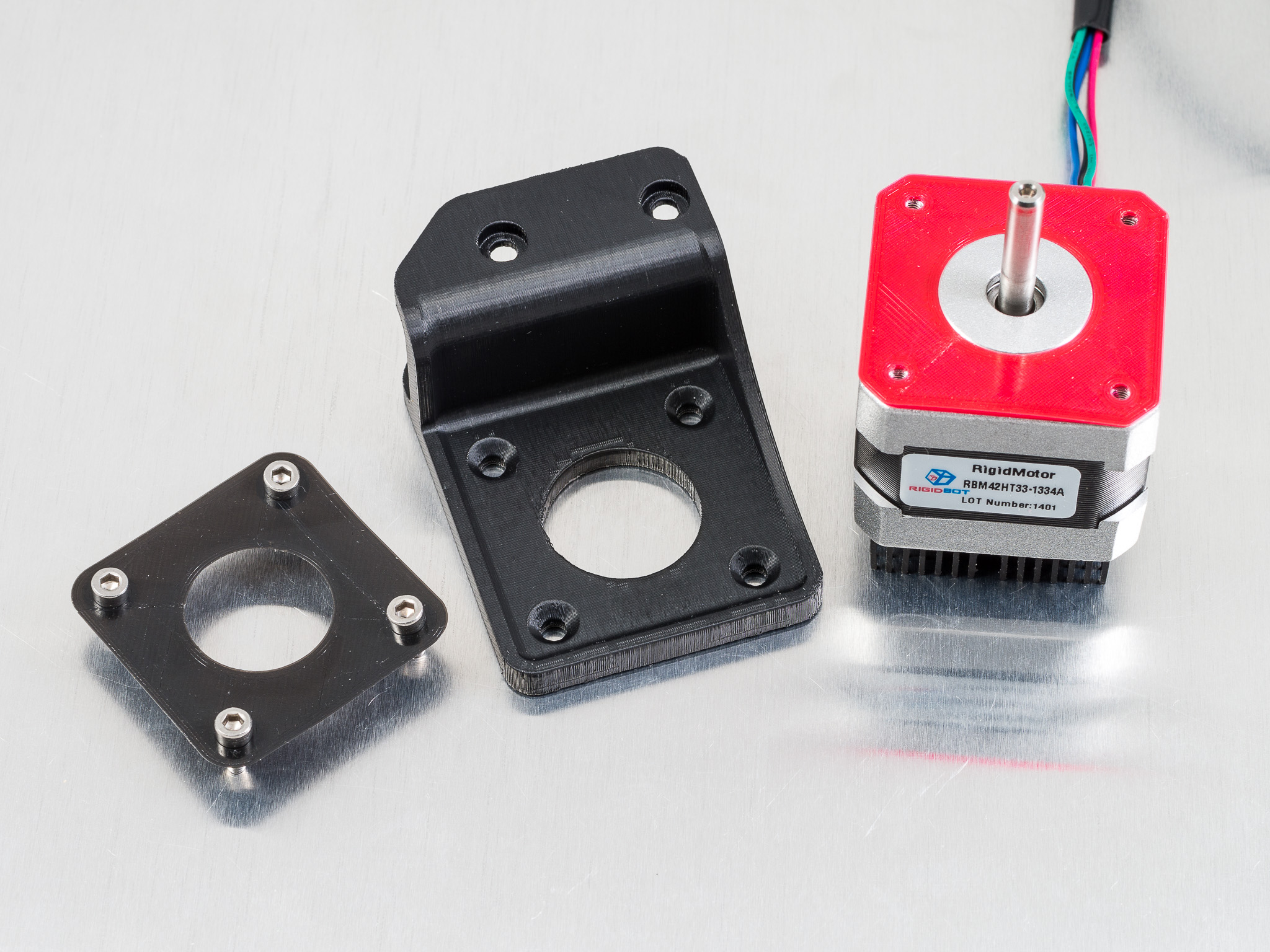
Offset Motor Mounts – Realigns driving half of the belt back to the original position when using a 16 tooth pulley. I also used NinjaFlex gaskets to isolate the stepper from the frame, which resulted in a small reduction in motor noise.
0.9 Degree High Torque Motors for X and Y axis [ebay]* [amazon]* – Increases the amount of torque, which lets you increase acceleration (make sure to increase both the default and max acceleration values), and decreases the chances of layer shifting from the printhead getting caught in the print. Faster acceleration decreases print time, but more importantly, gets rid of the corner blobbing and stringing caused by low acceleration (the default Rigidbot acceleration settings were really low). The higher resolution stepper doubles the frequency of the vertical banding artifacts, making it less objectionable.
Idler Pulley Upgrade – I replaced the X and Y axis idlers with the a new idler plate and OpenBuilds idler pulley kit thanks to Alex Lee. This reduced drag caused by the belt rubbing against the idler mount, enabling faster speeds and acceleration.
Adjustable Mobius Belt Tensioner – I use this belt tensioner on the Y-axis, it allows the belt tension to be adjusted with a screw. I have also twisted the belt 180 degrees so the smooth side of the belt runs along the idler bearing, instead of having the teeth running along the bearing. Some info online indicate that belt teeth on smooth idler pulleys may be an issue, but I didn’t see any difference from this change.
Z-axis Serial Motor Wiring PCB – I switched to series wiring for the Z-axis motors thanks to the PCB adapter board from Peter Stoneham. I had been running at 6mm/sec (up from the default of 4mm/sec) without any issues. After upgrading to series wiring, I doubled the z-axis speed to 12mm/sec, and that seems to be working (it may support faster speeds, but I didn’t try).
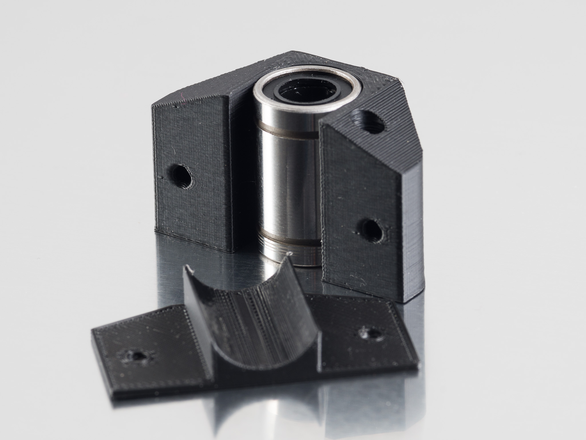
Z-axis Bearing Holders – I switched to longer linear bearings on the z-axis (LM8LUU*) and replaced the hearing holders. I did not notice any difference from the change.
Z-axis Limit Switch Adjustment – I added a screw to the Z-axis bearing holder over the z-axis limit switch, the allows for quick adjustment of the nozzle height, which is useful as the bed changes in height slightly at different temperatures.
Y-axis Bearing Holders – Swapped out the heated bed bearing holders, It probably didn’t make any difference.
Extruder
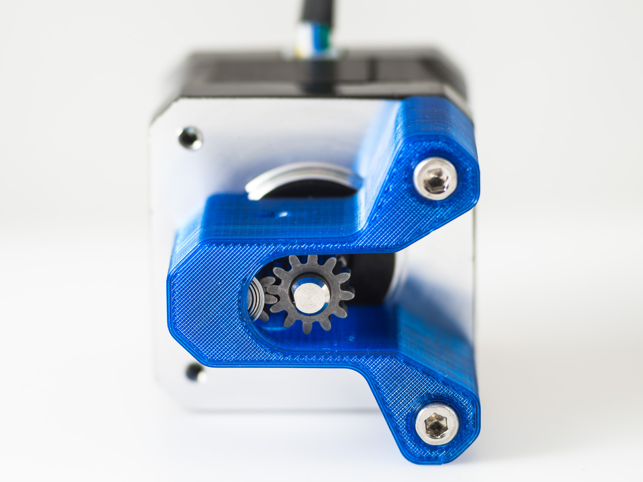
Printrbot Gear Head – Personally, I prefer fixed spacing, symmetric drive systems, I think it removes several of the variables affect extrusion rate leading to better quality and reliability. With spring loaded drive gears, factors like filament ovality, filament hardness, and changes in spring tension over time can affect the extrusion rate. The symmetric drive systems can also generate more nozzle pressure and I find them to be much more reliable. On the other hand, it can be less convenient, less tolerant of out of spec filament, and may require more torque. I’ve been very happy with the extruder built around the Printrbot Gear Head drive gears and a higher torque motor. Unfortunately, I don’t think Printrbot sells the gears separately anymore, only as part of a full extruder kit. Bondtech has some direct drive extruder gears that could be used as an alternative.
E3D v6 Hotend – I switched to the E3Dv6 (not the lite version) since it seemed highly regarded, and it has worked well for me with many types of filament. It enables printing with higher temperature plastics and is less likely to suffer a meltdown. PrintedSolid and Filastruder are good places to get one in the US, the RigidBot uses the 24V 1.75mm Universal version. I would avoid buying from anyone that isn’t on E3D’s genuine reseller list as there are many counterfeit versions out there.
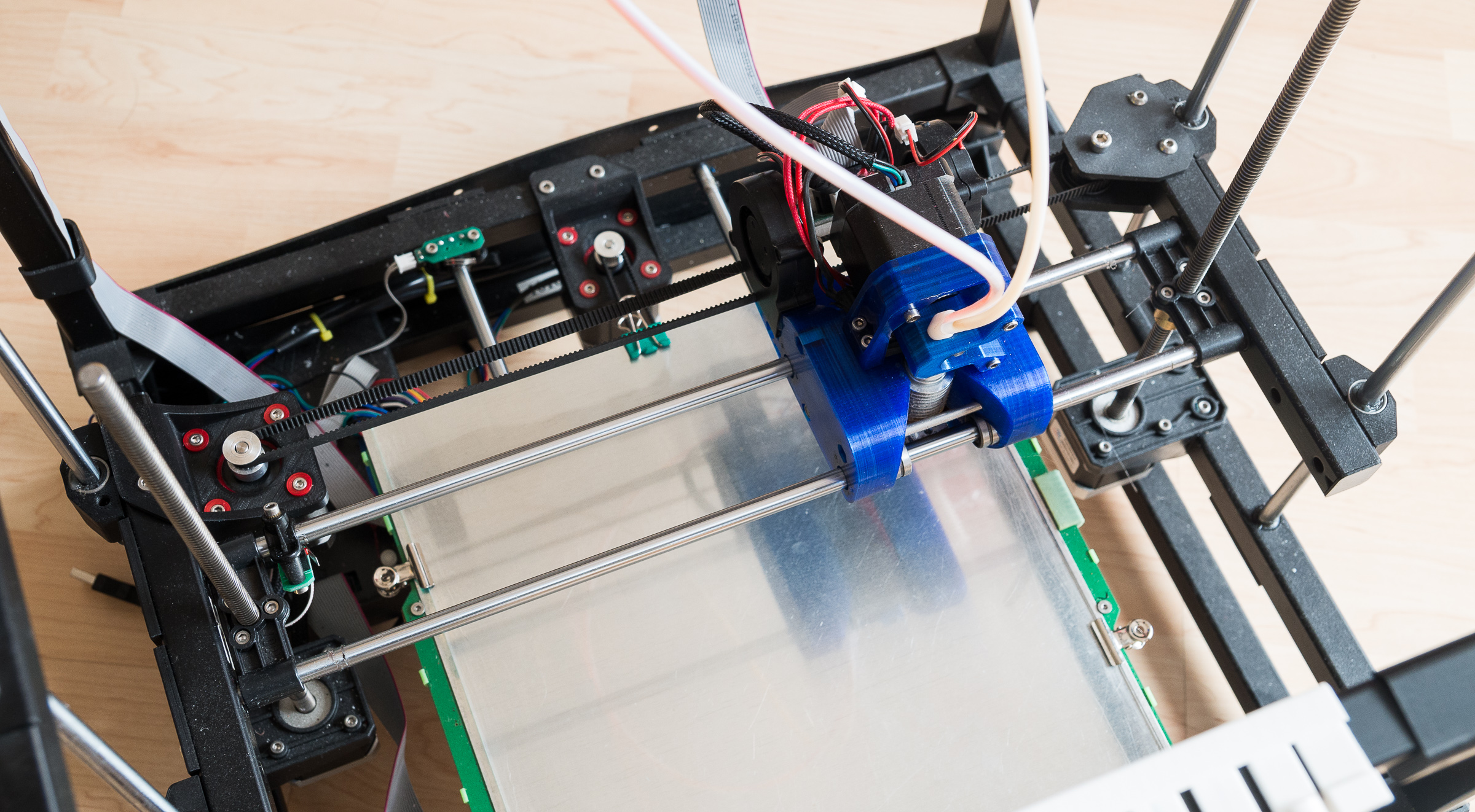
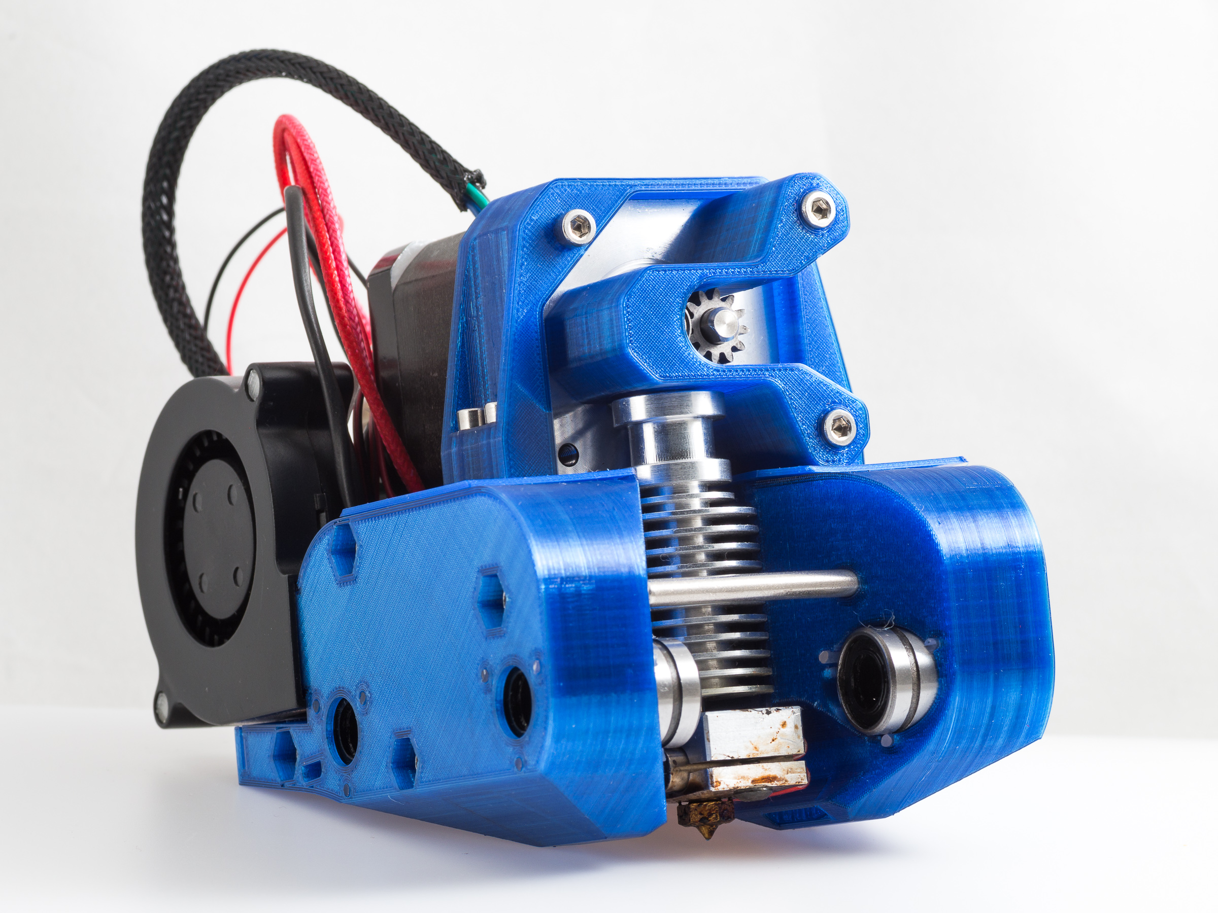
Tank Extruder Carriage – After trying out several extruder designs, I thought I’d try one with an excessive amount of cooling (two 50mm blower fans), and with the parts isolated from one another with NinjaFlex (based on some online suggestions that this would reduce vertical banding). It turns out I much prefer symmetric cooling, it improved print quality dramatically, and helped with ABS warping. Replacing the extruder also completely eliminated the vertical banding that would occasionally appear in prints, though I can only guess at why and I’m not sure about it’s repeatability (I think the motors/steppers were causing the banding, so this is somehow masking it, not solving the root issue). I’ve tried many different extruder designs, some of which have been uploaded to Thingiverse, but this is the only one I’ve really been happy with. I don’t think any of the previous designs lasted more than a month before being replaced. It’s very much geared towards my printing needs though, and there are many other options out there.
0.9 Degree High Torque Extruder Motor [ebay]* [amazon]* – I wanted to try a higher resolution extruder motor, based on online reports that print quality improves with higher microstepping rates, so I used the same motor I used on my X and Y axes. I’m not sure I can see any benefit to the extra resolution, but I like having the extra torque, it helps when printing at 100% infill, with small nozzles, metal filament, etc. This motor increases the weight of the extruder carriage, but it’s probably still much lighter than the heated bed.
Print Bed
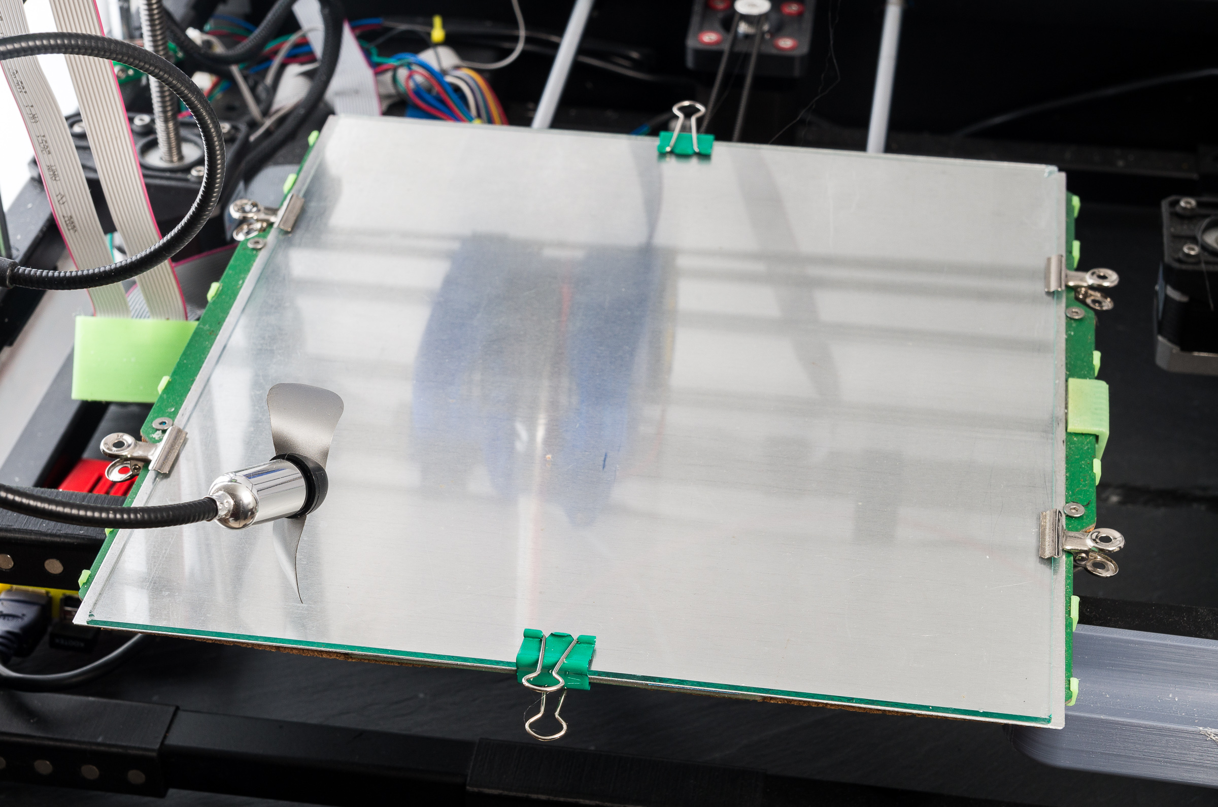
Heated Bed Stack – Based on a post from Alex Lee, I rebuilt the heated bed without the original aluminum plate. The new stack has cork* under the PCB, a thin sheet of aluminum over the PCB, and a glass sheet on top. I covered the top of the PCB with tape to insulate it from the aluminum sheet, to reduce the risk of a short against the aluminum heat spreader. The new bed stack reduces the weight of the heated bed, dramatically reduces heating time (it’s still slow), and enables higher bed temperatures (over 110°C).
Aluminum Heat Spreader [mcmaster] – The thin (1/64″, 0.4mm) sheet of aluminum helps spread the heat. Before adding the heat spreader, blowing air over the thermistor would cause the rest of the bed to overheat.
Glass Build Plate [home depot] – I prefer using a removable glass build plate. I tried polycarbonate, which I prefer on the Afinia, but at this size it warped too much to be effective.
Heated Bed Cable Clip – Plastic clip to prevent the heated bed cable from accidentally pulling out, I’m not sure it actually helps it may just be more flammable plastic to feed the fire if the connector does catch on fire.
Cork Clips – Long clips under the cork to secure it to the bottom of the heated bed PCB.
Binder Clips – I’ve found securing the heated bed on the sides near the screws make the z-height more consistent with temperature fluctuations.
Filament Path
Filament Guide Tubes – Helps the filament spool feed at a consistent rate, reduces tugging on the extruder, and reduces the risk of filament coming off the spool. I prefer 3mm inner / 4mm outer diameter PTFE tubing for this, which is what the Afinia uses for its guide tube.
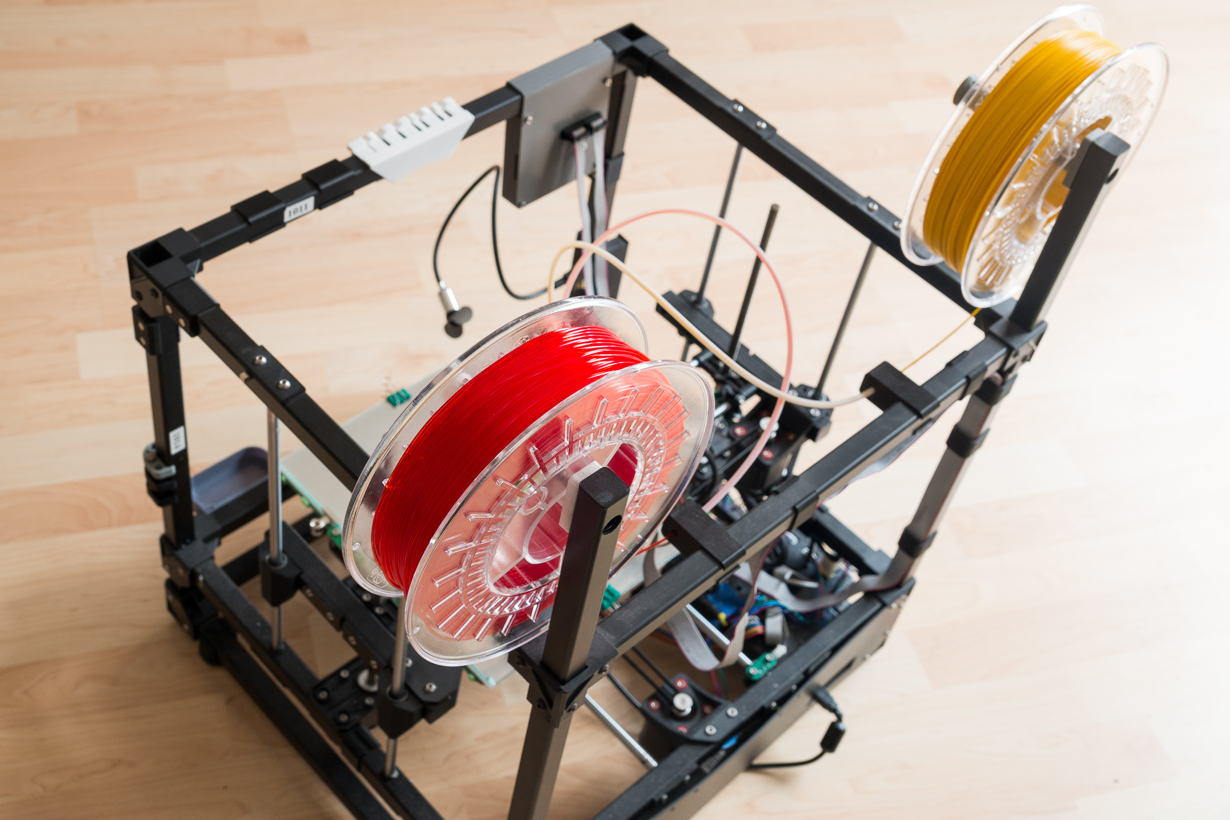
Spool Holders – I use two hanging spool holders to make filament changes faster, I never tried the included spool rack. I generally remove the filament when I’m not printing.
Frame

X and Y Axis Rod Holders – I tried replacing the Y-axis rod holders with ABS ones, thinking that the extra rigidity may help, but it significantly increased the vibrations on the bed (as measured by the accelerometer in a smartphone). So I went the other way and replaced the X and Y axis rod holders with ones made from PolyFlex and found it made the printer a lot quieter.
Z Axis Rod Holders – I replace the Z-axis rod holders with ABS rod holder to reduce flex in the Z-axis rods from momentum of the X-axis gantry. I don’t know if it made any difference.
Frame Knuckle Plates – These are just decorative plates, with an optional magnetic tool holder built in.
Wire Routing Clips – Clips in different sizes to help with cable routing.
Sorbothane Feet – Clip on Sorbothane feet. Others have found it to reduce printer noise, but I didn’t notice any change (probably because of other changes I had made previously).
Bar End Cover Plates – Hides the rust inside the metal bars.
Magnetic Tool Holders – Good for holding binder clips and hex wrenches.
Nozzle Rack – Stores extra nozzles and helps you remember which nozzle is installed.
Stainless Steel Screws [trimcraft] – I prefer stainless steel hardware so I replaced most of the screws with their stainless steel equivalent.
Other

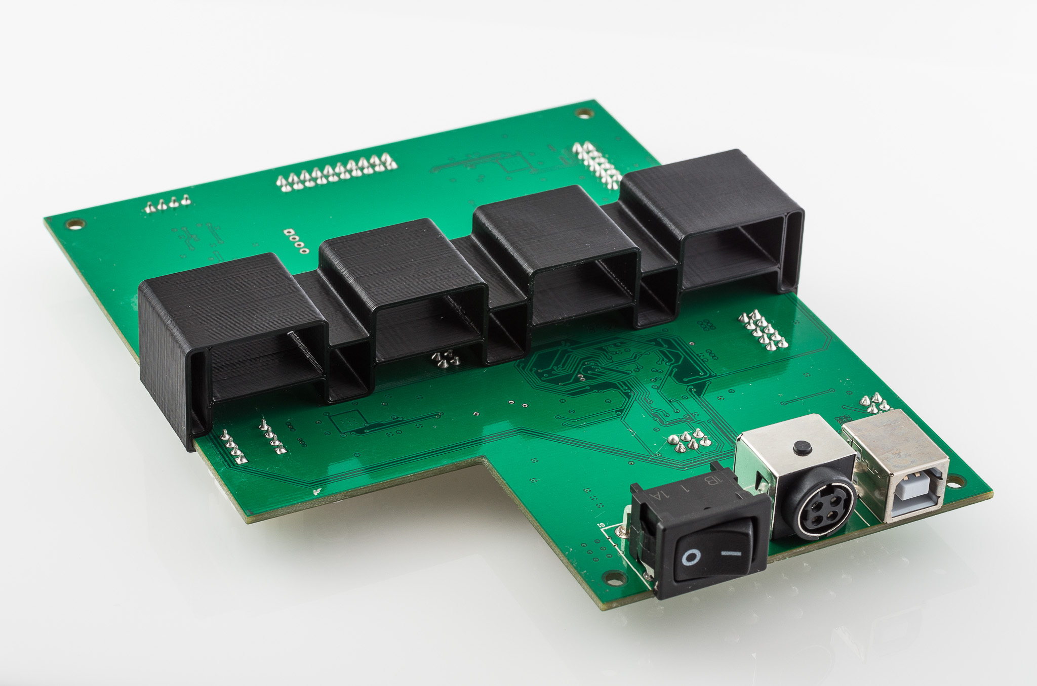
LCD Screen and Adapter Board – Many thanks to Marvin Stuart, who designed an adapter board, and put together a non-profit group buy for the LCD. I mostly use it for monitoring the printer temperature.
LCD Screen Case – Case for the LCD screen.
Replacement Power Supply – Upgraded the power supply to something quieter, there are a lot of similar options here from a high end Meanwell to a cheap unit on Aliexpress. It should be 24V and at least 400 watts and will require the cable from the original power supply or a new connector [ebay]*.
Power Supply Cover – Adapter cover to use standard power cords and includes a power switch.
USB Hub Mount – For mounting a USB hub with switches, which I use for USB fans and lights [amazon].
USB Fan [amazon] [dx]* – Attached a USB fan to speed up the drying of hairspray. It can also be used as an extra directional part cooling fan.
Mainboard Support – Added a supporting plastic part under the mainboard to prevent it from flexing when plugging in the cables.
Mainboard Fan [amazon]* – Added a 24V 60mm x 10mm fan* to the mainboard case to prevent overheating, it plugs into the bottom fan connector on the mainboard. I was not having any problems with overheating, I just added it as a preventative measure.
Removed Solder Bridges – Removed some solder bridges on the mainboard pots that were preventing the second extruder motor from working.
Octoprint – I control the printer with Octoprint, running on a Raspberry Pi*. It’s more convenient than using an SD card and allows me to continue using my printer normally when printing. Thomas Sanlanderer has an excellent video guide for setting it up.
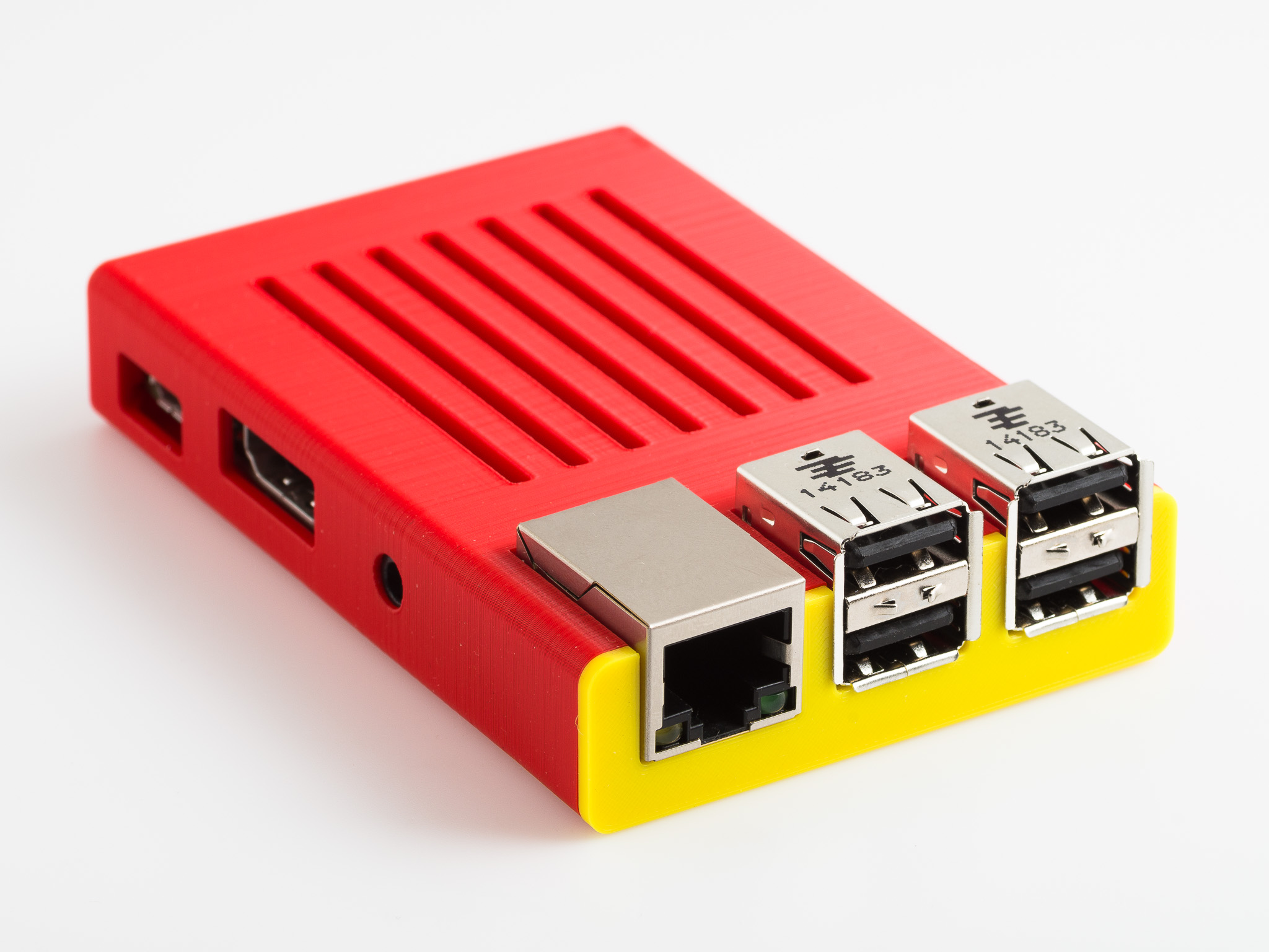
Raspberry Pi Sleeve Case – I use a simple case to protect my Raspberry Pi* from falling screws.
RigidBot Community Logo – Just in case I forget which of my printers I’m looking at.
Other Mods
There are some mods that I probably should do, but they’re in this section because I haven’t done them.
Replace Heated Bed Cable – The heated bed cable is prone melting or catching on fire, especially on the larger Rigidbots. I should replace mine, but I haven’t.
Y-axis 16X Microstepping – Some users have changed their y-axis motors to run at 16X microstepping instead of the default 8x microstepping. Seems like a good idea to have the same steps per mm on both X and y axes, but I haven’t changed mine (mostly because I hate soldering surface mount components).
Firmware
Here’s some of my firmware defaults:
Baudrate: 250000
Steps per unit: M92 X200.00 Y100.00 Z1600.00 E121.25
Maximum feedrates: M203 X500.00 Y500.00 Z12.00 E300.00
Maximum Acceleration: M201 X3600 Y3600 Z100 E10000
Acceleration (S=acceleration, T=retract acceleration): M204 S2000.00 T1200.00
Advanced variables (S=Min feedrate, T=Min travel feedrate, B=minimum segment time, X=maximum XY jerk, Z=maximum Z jerk, E=maximum E jerk): M205 S0.00 T0.00 B20000 X12.00 Z0.40 E5.00
Profiles
I use Simplify3D as a slicer. I always customize my settings to each print, but here’s my starting / default settings. I use different PID settings for different plastics, and enter them in the starting gcode.
Pictures of Modifications
About half of these prints were done on the Afinia, the other half on the Rigidbot.


RigidBot Prints
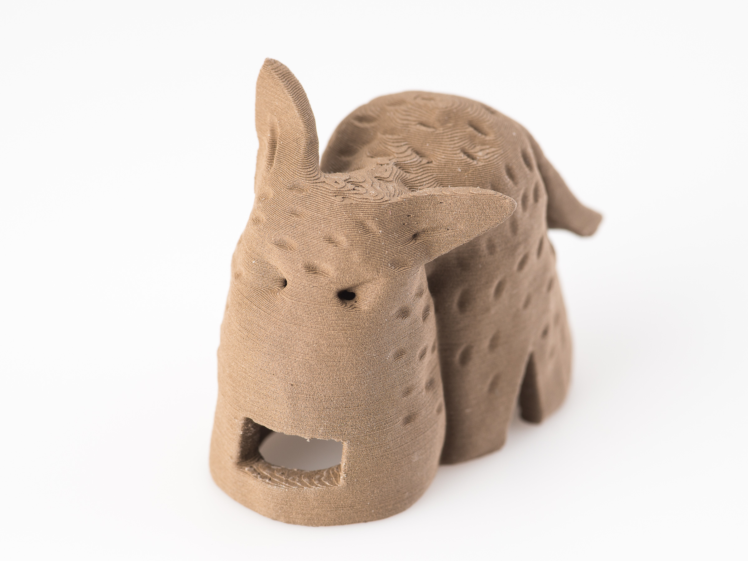
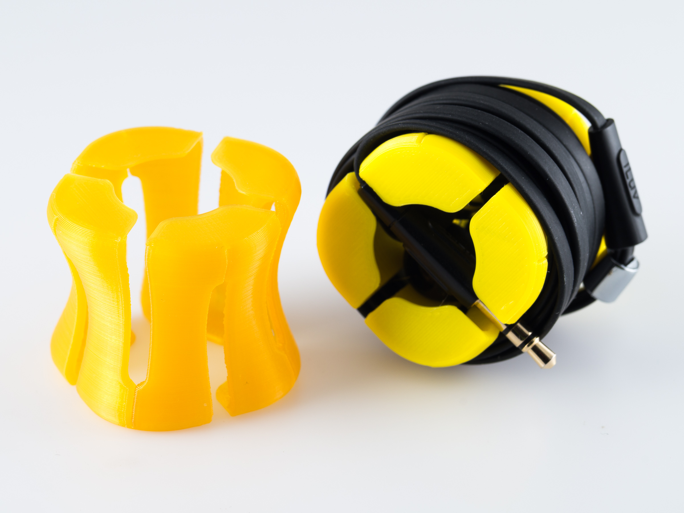
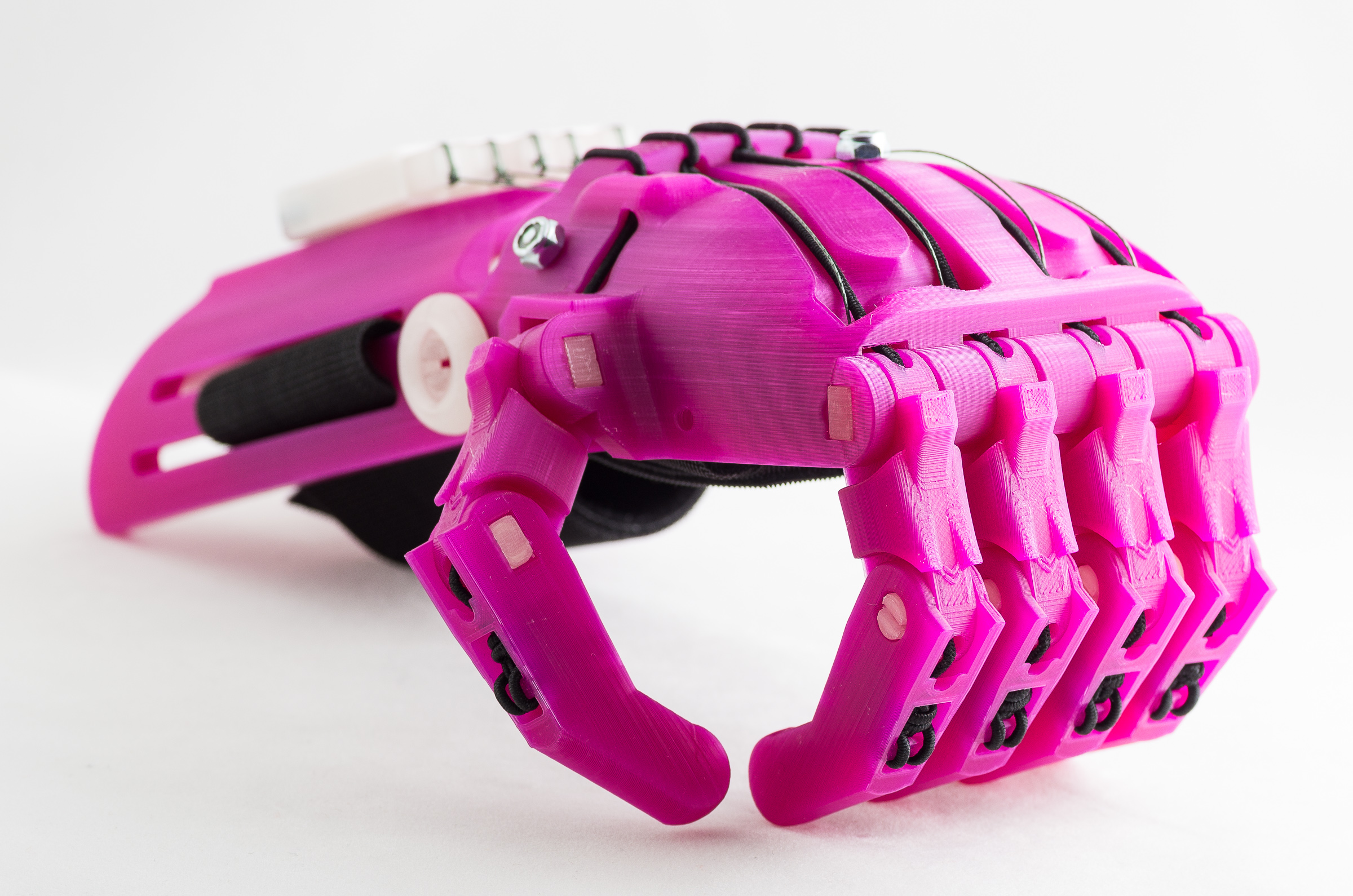
High resolution pictures of prints to give you a sense of the quality a Rigidbot is capable of. These prints were made in various stages of my printer’s life, not necessarily after all the changes above have been implemented. None of the prints have had any post processing done, other than removing support material on some of them.


These pictures include designs from the following talented designers: